

MakerX The Columbus Maker Expo will take place on April 21, 2018. Full details, including the call for exhibitors and venue information, can be found at:
MakerX is an independent maker festival that consists of a celebration, learning, and networking event for everyone in interested in the exciting new technologies of digital design and fabrication.
We are now accepting proposals to exhibit at MakerX!
We are seeking exhibitors who are: makers, inventors, tinkerers, teachers, clubs, meetups, hobbyists, professionals, makerspaces, schools, universities, start-ups, and corporations who want to share their knowledge of the world of digital design and fabrication.
The list of what we would like to see at MakerX is equally long and open ended. It certainly includes robotics of all sorts, drones, 3D printing and other digital prototyping and production technologies, electronic technology of all vintages, digital art and music, entertainment technologies, engineering innovations, game development, industrial design, AR/VR/mixed reality, digital biohacking, high-tech manufacturing, and technologies of citizen science.
In addition to this core we invite exhibits that round out a stimulating and fun event and remind us where our digital age has come from and where it may go: for example, cosplay of the sci-fi and steampunk variety, production crafts like blacksmithing, steam engines, DIY vehicles and art cars.
Tickets to attend MakerX will be available in January. In the meantime, please check it out at www.makerx.org, submit your proposal by December 1, and pass this announcement on to anyone you think might be interested.
MakerX is an entirely volunteer effort. Event contact: Bill Ball, billball@capital.edu.

If you want to have your own PCBs made you are free to do so as long as you keep the tinkerfarm.net as the only website on the silkscreen. This includes for commercial use. The Gerber files can be found here. The original blog post specified the manufacturer I used in China and I will note that I never had a problem with them across several orders.

It can easily be scaled to fit your space and plant, although 50% is probably the realistic minimum size. The full size version works well on a window sill.
This is three-piece print is designed to print well on any 3d printer without supports. If you have it, it is a good idea to use a second color for the float to make it more visible.
More information can be found on the Easy 3D Print page. The STL files are available on Thingiverse.

I have developed a introductory workshop to the Arduino world using the Circuit Playground. At the moment I am offering this workshop at the Columbus Idea Foundry. Materials for the course can be found under the workshop tab on this site.
The situation I faced was probably not that unusual so I thought I would share some thoughts and pictures on how I dealt with it.
I have a basement space of just over 200 square feet. The basement has a “floating floor” which is not attached to the walls and is far from level. The idea is that any water pressure that builds up on the outside will slowly seep through and out some drains in the floor. It seems to work, but it means nothing is level and it would be a bad idea to attach anything (especially anything conducting electricity) to the walls. Like most basements, it has low ceilings. Since this house is almost 100 years old there are also large ducts for the add-on AC and several generations of wiring running along the bottom of the joists. Despite this, things turned out ok. I detail my approach in the picture captions that follow.
 The raw space. After removing an old store room I began to chalk out the locations of work tables on the floor. I would use these to set the locations for lights and outlets on the floor joists above.
 A reverse angle on the raw space. I have begun to transfer the floor chalk marks to the joists. By mounting lights & outlets to the joists above I keep them away from the walls and basement floor. The glass block window has an unused vent that may come in handy some day.
 The work tables starting to go in. I used 3 of these 72″x24″ tables for tool stations and one for a workbench. Adjustable height legs are useful. Floor leveling feet are an absolute requirement here since every slab of this floor tilts at a different angle.
 This was a major score. A 72″x36″ proper electronics workbench I found at a local office surplus store. Getting it home and into the basement alone was……interesting.
 Almost everything set up. I used an online lumen calculator set to a bright office with dark walls to estimate the lighting. Eight BR40 bulbs fit the narrow and deep spaces between the joists. I went with 4000k high CRI LEDs, which give awesome light and are plastic, cool, and low energy to boot. Ceiling outlets provide drops to power strips on each bench. Lots of rolling storage with nothing on the floor. It’s already full. Typical 🙂
 And now for some fun. I don’t know how filament will fare in this high humidity environment (when it’s rainy, at least), but one challenge at a time.
But I finally scored this one for much less than that.

It’s a radio signal generator built for the Navy in the 1950s. Since it looks like a prop you would see in a Sci-Fi movie from the 50s or 60s, my plan is to make it work like it would have in Sci-Fi land. In other words, keep the knobs and dials but have them run blinking lights video clips and sound effects reminiscent of those movies. I hope it will be a hit at Makerfaires of the future.
The first stage was tear down. This proved quite entertaining in it’s own right. This piece of equipment was clearly built at high cost to be used and serviced by people with minimal training in a hostile environment. It’s made from dense anodized aluminum. Every knob has two set screws holding it in place. Every nut is a lock nut. The vacuum tubes were both sleeved and caged. There was wire wrap every inch or so on the harness. It weighed about 40 lbs. Everything comes apart–nothing is glued or otherwise sealed. It even has the schematic riveted to the inside of the outer case.
Here are some photos of the tear down into major components. I offered the tubes and other major parts on Ebay but there were no takers. So they went into the bin. The front panel, its support, and the outer case will provide ample opportunities to add modern micros, video screens, blinky lights, and powered speakers.


I really like Flipboard, it combines the best of traditional and new media without all the fear mongering that dominates the broadcast world. Flipboard also gives users a convenient way to create their own “magazines” of curated content and share them. Thus I have created a Flipboard magazine that encompases the interests reflected on this site. Please check it out if you are a Flipboard user.
I’ve created a new project category for tinkerfarm.net: Easy 3D Prints. These are simple, but functional, objects suitable for printing on pretty much any 3D printer. As the collection grows I may include some that require a commonly available non-3D printed part or two. But the point is to keep things as simple as possible. In addition to detailed descriptions on the project page, all files will be shared on Thingiverse and other repositories.
The advent of the dirt cheap ESP8266 chips and modules combined with porting of the the Arduino system to them offers an intriguing path forward. Starting several months ago, I worked with a partner to develop some robotic car prototypes around the ESP8266. At the time we were looking at a very low cost educational platform for introducing computer programing that would require no installs since it would all be done in a web browser. While I focused on the chassis and components, my partner developed the custom circuit board and some really slick interface applications.

That project is on hold, possibly forever, since many similar products have come on the market. However it clarified to me that I would be really struggling to become competent on developing for the remote devices (i.e. phones and tablets) that would be controlling the robot car (or other IoT things). Also, pure web interfaces can be clumsy on one hand, yet Apple has made it far from easy to produce iPhone apps, on the other.
Meanwhile a number of projects have launched that are designed to make it easier to develop IoT apps/devices for people who are not professional-level programmers. I now have a box of their hardware platforms after backing too many kickstarters :). It’s still pretty much a wild west environment out there, but I think things are beginning to settle down a bit.
One system for easy IoT that appeals to me is Blynk. Blynk has several things going for it:
But does it work? As a first attempt I rebuilt one of our robotic car chassis with a ESP8266 in the NodeMCU carrier format, mounted to a motor driver shield (from doit.am). I installed the Blynk app on my Android phone and modified one of their example apps to upload to the NodeMCU via the Arduino environment. Success! Sort of! I could run the motors up and down with the Blynk app on my phone. However I was running it through their servers and the network lag made the car uncontrollable. So far, I have not gotten the direct access mode working were the phone connects directly to the ESP8266 running as an access point. That should solve the lag problem.
So I am going to start a project to learn IoT using a home automation type demo. It will probably be a combination of lighting, environmental sensing, and perhaps notifications. This will be on the ESP8266 platform with Arduino + Blynk and using commonly available and cheap sensors and probably 3D printed housings. I will post all the details to a project web page on tinkerfarm.net
Having previously covered the development of the LED module and the lamp designs, this post will touch on the assembly of the components and the method of distribution.
The PCBs were designed in Fritizing and manufactured by PCBWay. Although I knew this project would be hand assembled, I wanted to approximate a manufacturing process as closely as possible. As a result, only surface mount components were used on the board. These were added with the aid of a solder paste stencil cut from overhead transparency plastic on a Cricut machine. The boards were finished in a small PCB oven, although a significant number needed touching up with a hot air rework gun. The USB jack proved troublesome to position correctly with its very small wires. I had planned to include the heat sink in this stencil and heat process but the oven I used was not able to overcome the thermal mass of the sink and reflow the solder fully. In the end I used thermal paste to manually glue down each one. The LED was glued and then hand soldered on the other side.
Each module was tested for polarity and continuity before installation of the LED and tested again afterwards with a USB cable to make sure it fit and lit up properly.
Kitting began with finding very small bags for the screws and filling them. I included a couple extra screws in each bag since they are so small and easy to lose.

Once the lamp designs were finalized and tested, it was time to assemble the final kits. Since I have had very good luck with selling my prototyping boards on Ebay and very little success with them on Tindie, I decided to make the LED module kits available on Ebay, even though the selling costs are higher than on Tindie. The 3D printing files I have uploaded to Thingiverse in the past have been frequently downloaded so that was the repository that made the most sense for the lamp files associated with this project. In fact I am assuming that Thingiverse will be the primary place where people will discover this project and then they will purchase the LED modules from Ebay to go with their prints, and perhaps read about the project on this site.

I have 50 sets of LED modules up for sale and we will see how it goes…..
This process started with a design for a ring to mount the LED module to and a corresponding clip that would be part of a lampshade that the ring with mounted LED would clip into. The 3D designs were done in a combination of 123D Design and Tinkercad.
The ring/clip combination took a considerable time to develop, given the heat generating capabilities of the LED module and the low melting point of 3D printed plastic, especially PLA. A number of designs were developed and tested that minimized the contact between the module and the 3D printed ring, provided protection from fingers touching the back of the hot modules, provided ample air flow, yet minimized size and offered ease of installation.
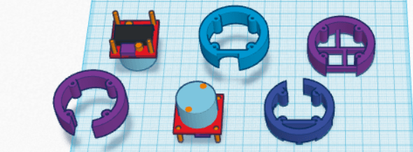
Once the ring was finalized the basic clip could be created by subtracting a ring from a cylindrical blank in 3D space. However the notion of using tabs that would flex on the clip as the ring was inserted created a lot of difficulty when using brittle filaments like PLA–the tabs tended to break if the fit was too tight. A large number of tiny revisions of the slots for the tabs on the ring were required to achieve the best compromise of good fit with minimal risk of breakage.
Thanks to my membership in multiple makerspaces I was able to test these designs in both ABS (good) and PLA (acceptable) on a wide variety of 3D printers. The primary work was done on a Stratasys uPrint SE using ABS but that was then tested on consumer-level printers from Makerbot, Makergear, Ultimaker, Deltamaker, and Printbot in PLA since most of us don’t own a $25,000 Stratasys. Ultimately small compromises were necessary throughout the 3D design to achieve acceptable fit on all parts of the lamp assembly across these printers.
I wanted to offer a variety of lamps that the ring with a LED module could clip into. I ultimately chose a desk or reading lamp, a decorative lamp shaped like a rocket, and a general utility lamp that would be the quickest and easiest to print. I am also making the ring and clip available on their own for people who would like to design the clip into their own shade.
The most problematic feature of developing the lamps was again finding the right compromise of fit among parts that would allow a firm fit without easy breakage, especially in the pivot points on the desk lamp and the utility light. Fancy adjustment plans involving sliding clips and ball sockets also had to be abandoned in favor of a simple hole-and-pin connectors . PLA is just not friendly to parts that have to flex! I hope a less brittle filament eventually becomes the standard for low end printers.
The desk lamp presented additional problems in achieving adequate height with a sufficiently stable base while keeping print time low.

Once the 3D designs were finalized and printed for product pictures, it was on to kitting and putting it out there in the world….
The process of designing an prototyping the lamp module will be the focus of this post.
In developing the lamp module there were at least 11 goals, which is a lot for a simple little light:
It took a couple of months of tinkering with LED modules, heat sinks, resistor values, circuit board designs, usb jacks, lenses, and even types of mounting screws to come up with a final design. The big bear was #9, heat generation. It took a combination of juggling all of the above plus the design of the 3D printed mounting ring to arrive at a lamp module that would not melt PLA.


The final design is certainly not perfect but functions well enough that I ordered 50 PCBs and 50 sets of components to make up a batch for testing and test marketing.
On to the lamp designs for 3D printing…………….


Here is another little toy for Orlando Makerfaire 2015. It’s more derivative that the things I usually make but still fun. The original is Theo Jansen’s Standbeest sculptures. The more immediate inspiration was a motorized toy one featured in Servo magazine awhile back.
This uses two continuous rotation servos to drive the legs, steered by two Sharp IR sensors and controlled by an Arduino pro mini.
The closer you get the more frantic it gets. If you get all the way up to it at present it just gets calm again, but I am planning to add a surprise or two for makerfaire.

A limited number of these stands are available on Etsy. Or you can print yourself one in plastic using the 3D file on the project page.

In the meantime I have this neat box of boards sitting on my desk just asking to be put to work in projects……

I have started a page of links to maker skill tutorials published by others here. It is a highly curated list of tutorials that I feel are accessible to beginners, relevant to the kind of maker projects provided on this site, and from reliable sources. Moreover, the focus will be on basic processes and components of commonly used hardware rather than projects, complex systems, software, or specific brands. At the moment, it contains a good list for electronics. I will be adding other subjects over time.