Developing the Tinkerlight: Assembly and distribution

The Tinkerlight is now available. A limited number of LED module hardware kits are for sale on ebay and the 3D printable lamp files are on Thingiverse. The full product page, with links to the hardware kit and designs,  is here.

Having previously covered the development of the LED module and the lamp designs, this post will touch on the assembly of the components and the method of distribution.

The PCBs were designed in Fritizing and manufactured by PCBWay. Although I knew this project would be hand assembled, I wanted to approximate a manufacturing process as closely as possible. As a result, only surface mount components were used on the board. These were added with the aid of a solder paste stencil cut from overhead transparency plastic on a Cricut machine. The boards were finished in a small PCB oven, although a significant number needed touching up with a hot air rework gun. The USB jack proved troublesome to position correctly with its very small wires. I had planned to include the heat sink in this stencil and heat process but the oven I used was not able to overcome the thermal mass of the sink and reflow the solder fully. In the end I used thermal paste to manually glue down each one. The LED was glued and then hand soldered on the other side.

Each module was tested for polarity and continuity before installation of the LED and tested again afterwards with a USB cable to make sure it fit and lit up properly.

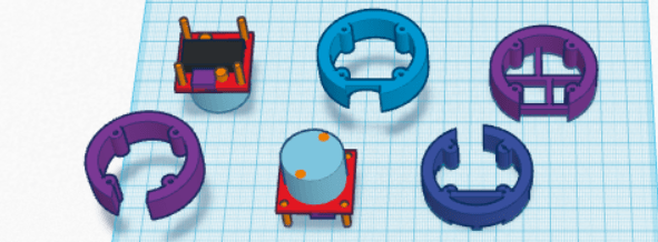
Kitting began with finding very small bags for the screws and filling them. I included a couple extra screws in each bag since they are so small and easy to lose.

Lots of small parts to lose while bagging.


Once the lamp designs were finalized and tested, it was time to assemble the final kits. Since I have had very good luck with selling my prototyping boards on Ebay and very little success with them on Tindie, I decided to make the LED module kits available on Ebay, even though the selling costs are higher than on Tindie. The 3D printing files I have uploaded to Thingiverse in the past have been frequently downloaded so that was the repository that made the most sense for the lamp files associated with this project. In fact I am assuming that Thingiverse will be the primary place where people will discover this project and then they will purchase the LED modules from Ebay to go with their prints, and perhaps read about the project on this site.

Final kitting. Turns out that dogs are not good at this task.


I have 50 sets of LED modules up for sale and we will see how it goes…..

Developing the tinkerlight: lamps

Having settled on the design for the hardware that would be made available on Ebay (the lamp module), the next task was to design some lamps that would be made available as free .stl file downloads via Thingiverse. The goals here were to provide some functional and (at least reasonably) attractive designs that would not take too long to print. I kept the maximum size of any piece to 6″ and designed around PLA filament printed with no  supports so these would print on the widest variety of printers.

This process started with a design for a ring to mount the LED module to and a corresponding clip that would be part of a lampshade that the ring with mounted LED would clip into. The 3D designs were done in a combination of 123D Design and Tinkercad.

The ring/clip combination took a considerable time to develop, given the heat generating capabilities of the LED module and the low melting point of 3D printed plastic, especially PLA. A number of designs were developed and tested that minimized the contact between the module and the 3D printed ring, provided protection from fingers touching the back of the hot modules, provided ample air flow,  yet minimized size and offered ease of installation.

tinkerlight ring_dev
Developing a ring/clip combo using mockups of the LED module.

Once the ring was finalized the basic clip could be created by subtracting a ring from a cylindrical blank in 3D space. However the notion of using tabs that would flex on the clip as the ring was inserted created a lot of difficulty when using brittle filaments like PLA–the tabs tended to break if the fit was too tight. A large number of tiny revisions of the slots for the tabs on the ring were required to achieve the best compromise of good fit with  minimal risk of breakage.

Thanks to my membership in multiple makerspaces I was able to test these designs in both ABS (good) and PLA (acceptable) on a wide variety of 3D printers. The primary work was done on a Stratasys uPrint SE using ABS but that was then tested on consumer-level printers from Makerbot, Makergear, Ultimaker, Deltamaker, and Printbot in PLA since most of us don’t own a $25,000 Stratasys. Ultimately small compromises were necessary throughout the 3D design to achieve acceptable fit on all parts of the lamp assembly across these printers.

I wanted to offer a variety of lamps that the ring with a LED module could clip into. I ultimately chose a desk or reading lamp, a decorative lamp shaped like a rocket, and a general utility lamp that would be the quickest and easiest to print. I am also making the ring and clip available on their own for people who would like to design the clip into their own shade.

The most problematic feature of developing the lamps was again finding the right compromise of fit among parts that would allow a firm fit without easy breakage, especially in the pivot points on the desk lamp and the utility light. Fancy adjustment plans involving sliding clips and ball sockets also had to be abandoned in favor of a simple hole-and-pin connectors .  PLA is just not friendly to parts that have to flex! I hope a less brittle filament eventually becomes the standard for low end printers.

The desk lamp presented additional problems in achieving adequate height with a sufficiently stable base while keeping print time low.

A big pile of failure in 3D lamp designs.

Once the 3D designs were finalized and printed for product pictures, it was on to kitting and putting it out there in the world….

Developing the tinkerlight: lamp module

I am developing a project for people with 3D printers who are looking for a functional design they can use around the house. The project is a LED lamp module that uses power from a USB cable. The module and a switched cable will be available on eBay at low cost with mounting screws and a lens. That will be accompanied by a series of free designs for different type of lamps posted to Thingiverse for people to download and print out to go along with the lamp module.

The process of designing an prototyping the lamp module will be the focus of this post.

In developing the lamp module there were at least 11 goals, which is a lot for a simple little light:

  1. Small size–a smaller module would mean smaller and thus faster prints for the end user.
  2. Low cost–I wanted to make this as accessible as possible, not to mention appealing for purchase.
  3. Minimal part count–fewer parts keeps cost down.
  4. Design for manufacturing–although I will be hand assembling these, I want to use manufacturable components such as surface mount electronics.
  5. High light output–the brighter the light, the more useful it will be.
  6. Neutral light color–since this may used as decorative light that shines through a 3D printed part it was important to keep it a neutral color (around 4000k color temperature).
  7. Good light dispersion–a nice wide field for decorative use but an even narrow beam for reading or task lamp. An accessory lens provides this flexibility.
  8. Appropriate power consumption–I did not want to exceed the 500mA limit for computer sourced usb, although I will not be encouraging people to power this from a computer.
  9. Acceptable heat generation–a bright LED in a small package generates heat concentrated enough to melt a 3D print, which is obviously unacceptable.
  10. Flexibility for different applications–I wanted to keep the type of lamp the module would be useful in as open as possible.
  11. Ease of use–I wanted to come up with a lamp module that could be attached to a wide variety of 3D prints with minimal hassle.

It took a couple of months of tinkering with LED modules, heat sinks, resistor values, circuit board designs, usb jacks,  lenses, and even types of mounting screws to come up with a final design. The big bear was #9, heat generation. It took a combination of juggling all of the above plus the design of the 3D printed mounting ring to arrive at a lamp module that would not melt PLA.

A big pile of failue
A big pile of failure, necessary to develop a good design.


LEDs were evaluated for color quality and heat output.


Tinkercad was a handy way of visualizing how all the parts would fit together prior laying out the circuit board.
Tinkercad was a handy way of quickly visualizing how all the parts would fit together prior laying out the circuit board.


tinkerlight board
The PCB was done in Frtizing with large copper pads all over just to help distribute the heat.


The final design is certainly not perfect but functions well enough that I ordered 50 PCBs and 50 sets of components to make up a batch for testing and test marketing.

On to the lamp designs for 3D printing…………….